By: Lucas
Tuesday, December 15, 2015
Monday, December 14, 2015
LAST DAY OF TROUBLESHOOTING!!!
Monday, December 7, 2015
Saturday, December 5, 2015
Progress Report on the Buggie Prototype...
Buggie
Concept sketch:
This is the primary sketch of an Arduino-controlled mini car nicknamed Buggie.
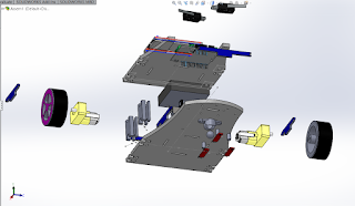
SolidWorks Assembly Multiple Views:

The first picture (top left side) shows the back of the car. It is possible to notice that it is two-wheel driven and it turns left and right by reversing the direction of rotation of one side. In other words, one of the wheels goes forward while the other goes in reverse.
The second picture (right side) shows the top of the Buggie. It has two chassis. On the top chassis, there is a breadboard. An Arduino Uno device, a motor shield, and two collision sensors are placed on the bottom chassis.
The third picture shows a trimetric view of the model.
The fourth picture (bottom right side) shows the car viewed from the side. It illustrates a Pololu low friction caster ball, which eases steering left or right. In front of it,there are three analog line sensors, devices that, when properly programmed, can cause the Buggie to follow a determined path. A case is also noticeable in the section in between the top and bottom chassis. It contains 4 AA 1.5 V batteries to power the Arduino.
Assembly Drawing
Drawing of the car prototype following ANSI standards:
Scale: 1:4
Format: Landscape (ANSI) size A
Drawing Mounting Parts:
Bottom Chassis
Scale: 1:2
Format: Landscape (ANSI) size B
Concept sketch:

The first picture (top left side) shows the back of the car. It is possible to notice that it is two-wheel driven and it turns left and right by reversing the direction of rotation of one side. In other words, one of the wheels goes forward while the other goes in reverse.
The second picture (right side) shows the top of the Buggie. It has two chassis. On the top chassis, there is a breadboard. An Arduino Uno device, a motor shield, and two collision sensors are placed on the bottom chassis.
The third picture shows a trimetric view of the model.
The fourth picture (bottom right side) shows the car viewed from the side. It illustrates a Pololu low friction caster ball, which eases steering left or right. In front of it,there are three analog line sensors, devices that, when properly programmed, can cause the Buggie to follow a determined path. A case is also noticeable in the section in between the top and bottom chassis. It contains 4 AA 1.5 V batteries to power the Arduino.
Assembly Drawing
Drawing of the car prototype following ANSI standards:
Scale: 1:4
Format: Landscape (ANSI) size A
Bottom Chassis
Scale: 1:2
Format: Landscape (ANSI) size B
Top Chassis
Scale: 1:2
Format: Landscape (ANSI) size C
Friday, November 27, 2015
Wednesday, November 11, 2015
First Official Post
This is Team Authentique's first official post. This blog is primarily used for posting and documenting design processes on SolidWorks.
For now, we are spending some time figuring out how to operate this interface and adding pictures.
For now, we are spending some time figuring out how to operate this interface and adding pictures.
These pictures were taken during a trip that I made to Washington D.C. at one of its numerous museums.
By: Lucas Fernandes
Labels:
First Post
Subscribe to:
Comments (Atom)


